Waterworks
Watermills feature sophisticated mechanisms and many fascinating details. Their operation was based on the use of the dynamic and kinetic energy of falling water which set in motion a mechanism that turned wheat into flour.
Typical watermills mainly consisted of two basic parts:
- the drop tower, a construction of considerable height, from where the water would fall and thus gain the necessary energy, and
- the main building of the watermill.
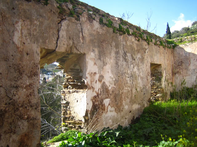
The main building of the watermill (no matter how large or small, simple or complicated) always included the following two parts: The lower part of the building (a basement called zourio) contained the spinning wheel, the first component of the mechanism to receive the energy from the falling water. The zourio was a low ceiling space, where a person could only stand crouched over. The miller could handle the whole mechanism from the ground floor and entered the zourio in the event of damage or malfunction of the wheel. The flowing water would turn the spinning wheel that was connected by a vertical wooden axle to the two millstones that ground the wheat, on the ground floor. Therefore the ground level was kept completely dry, as the falling water would enter from the drop tower directly to the basement and from there it would exit the main building.

Hydria Virtual Museum

Hydria Virtual Museum

Hydria Virtual Museum

Hydria Virtual Museum

Hydria Virtual Museum
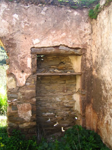
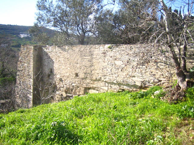
The buildings of the watermills were usually built with limestone and mortar (lime mortar, clay or sand). The simplest watermills consisted of a single-space rectangle building with a basement (zourio) and a series of stone-built arches supporting the roof. But there are also many multi-storied watermill buildings, with several rooms. The roof was usually made of branches, canes and earth, or of large schist slabs supported by beams. In some cases, a small house for the miller was attached to the watermill, which indicates the constant operation of the watermill throughout the year. Also, the interior of the watermill often included a fireplace and built-in shelves.
Hydria Virtual Museum

Hydria Virtual Museum

Hydria Virtual Museum

Hydria Virtual Museum

Hydria Virtual Museum
Hydria Virtual Museum

Hydria Virtual Museum
Watermills operate with quite an exciting system: Before reaching the mill, the water would flow into a narrow horizontal channel. At the end of this canal the water reached the vertical channel that was located inside the stone-built drop tower (canalio) and was therefore forced to fall from a total height of approximately 15 to 20 m (or even more in some cases). This vertical channel inside the drop tower was sometimes wider at the top and narrower at the bottom.

Hydria Virtual Museum
Hydria Virtual Museum
The lower part of the drop tower ended in a horizontal pipe, which was either built or carved in stone- (sfounara). Sometimes, this stone-built pipe was connected to another horizontal pipe, called sfouni, which was practically a hollowed-out plane –tree branch. This wooden pipe directed the water to a horizontal spinning wheel in the basement of the watermill. The spinning wheel was either wooden or metal. The wooden wheels (widely used in the region of Koronida) consisted of a series of wooden wings supported circularly on a plane tree log (sfontyli) at the centre of the wheel. The spinning wheel (wooden or metal) would start spinnig due to the energy of the water and transmitted its movement to the millstones through the wooden axlethat connected the two levels of the mechanism (basement and ground floor).

Hydria Virtual Museum
The wheat was ground between the two round millstones: The larger one stood in a fixed position with a hole in its centre through which the wooden axle passed. The smaller millstone, on top of the first, was connected to the wooden axle, which means that once the wheel started to turn, the upper millstone would turn as well. The wheat was therefore milled between the two stones and pushed to their perimeter by the centrifugal force of the spinning. From there it was collected in special containers.

Hydria Virtual Museum

Hydria Virtual Museum
The system used for inserting the wheat into the mechanism is also very interesting. A wooden container shaped like an upturned pyramid (cofinida) was located over the millstones, letting the wheat flow through a hole at the bottom. This container also included a sophisticated system for regulating the flow of the wheat. Underneath the lower edge of the container a U-shaped component was located (oula). A string was tied to the sides of this U-shaped component, which was supported to one side of the wheat container (on its exterior surface) and ended in a small piece of wood. The inclination of the U-shaped piece was regulated by this system and determined the quantity of the poured wheat. In the centre of the moving (upper) millstone a wooden cylinder (trohouli), was embedded, the upper base of which had a castellated surface. A small vertical wooden shaft (vardari), was fixed to the bottom of the wheat container, being forced to pass over the irregular surface of the cylinder, as the millstone turned. Therefore, with the spinning the wheat container would shake, forcing the wheat to fall between the two millstones, where it was ground.

Hydria Virtual Museum

Hydria Virtual Museum

Hydria Virtual Museum

Hydria Virtual Museum
The watermills also had a mechanism to determine whether the flour produced would be fine or coarse-grained. This was regulated by another vertical wooden compartment (anevatis): Its lower edge was connected to the base-board of the spinning wheel (trapeza) (made of wood or stone) and its upper edge would pass through the basement ceiling to appear on the ground floor, in the form of a handle. By lifting this wooden handle and supporting it in an elevated position using wooden wedges, the base of the overall mechanism was slightly “lifted” and therefore the upper millstone was also raised from the lower one, thus producing coarse-grained flour. For finer-grained flour, the anevatis would be set to its lower position, bringing the two millstones closer.
A similar wooden element (stamatiras) was also used to set the operation of the watermill on and off. This element was also placed vertically with its lower edge inside the basement and its other end visible on the ground floor. By lifting it, the wooden board located in front of the water pipe (sfouni) would be placed in such a position so as to divert the water from the spinning wheel to continue its way to the river. The rotating mechanism would then stop. The miller was able to use both these systems (anevatis and stamatiras) from the ground floor, without having to go into the basement.

Hydria Virtual Museum

Hydria Virtual Museum
Hydria Virtual Museum
Finally, the water used would be diverted back to the river. Usually, upon exit from the basement (zourio), a canal of considerable length would lead the water back to the river or to nearby gardens to be used for irrigation. The traditional watermill was therefore an environmentally friendly installation, with a mechanism that used solely the dynamic and kinetic energy of falling water, hence avoiding the consumption of raw materials in order to produce energy and avoiding also the production of any waste or by-products.

Hydria Virtual Museum